Key Preparations Before Integration
Before diving into wiring and coding, confirm you have all the necessary tools and components. Skipping this step often leads to avoidable errors (e.g., fried modules or no data transmission).
1.1 Required Components
| Component | Specifications & Purpose |
|---|---|
|
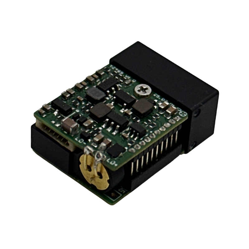
Laser Rangefinder |
TTL serial interface (3.3V), 0.8WTB-6Y-2 connector, 3m minimum range, 115200bps default baud rate |
|
AP-Compatible Flight Controller |
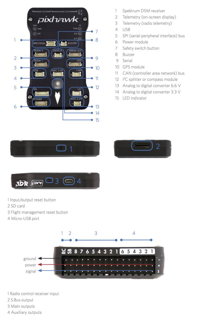
Pixhawk 2.4.8/4/6 (most common), with at least one free UART port (e.g., TELEM2, GPS2) |
|
USB-TTL Adapter (CH340) |
For testing the SFA2000B’s serial communication before connecting to the flight controller |
|
Shielded Dupont Wires |
To reduce electromagnetic interference (EMI) from the drone’s motors/ESCs |
|
External 3.3V/1A Power Module (Optional) |
If the flight controller’s 3.3V port can’t supply 500mA (SFA2000B’s peak startup current) |
1.2 Software Tools
- Mission Planner: The official ground station for ArduPilot (download here). Used to configure flight controller parameters and validate data.
- SSCOM/SecureCRT: Serial debugging tools to test the SFA2000B’s protocol (send commands, verify distance data).
- ArduPilot Source Code (Optional): For advanced users who need to compile custom firmware (e.g., 10Hz continuous ranging).
Step 1: Test the SFA2000B’s Serial Protocol (Critical!)
The SFA2000B uses a custom hexadecimal protocol (not MAVLink, ArduPilot’s native language). First, confirm the module works independently to rule out hardware defects.
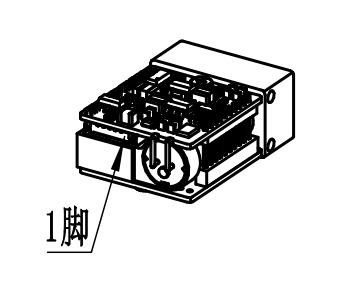
1.1 Wire the SFA2000B to a USB-TTL Adapter
Connect the module to your computer using a USB-TTL adapter. Follow the pinout from the SFA2000B’s datasheet:
| USB-TTL Adapter Pin | SFA2000B Pin | Description |
|---|---|---|
|
3.3V |
Pin 5 (VCC) |
Power the module (never use 5V—risk of burnout!) |
|
GND |
Pin 6 (GND) |
Common ground (critical for stable communication) |
|
TXD |
Pin 2 (RXD) |
Computer sends commands to the SFA2000B |
|
RXD |
Pin 3 (TXD) |
SFA2000B sends distance data to the computer |
1.2 Send Commands & Verify Data
- Baud rate: 115200bps
- Data bits: 8, Stop bits: 1, Parity: None
- Check “Hex Send” and “Hex Display”
Test 1: Single Ranging Command
55 AA 88 FF FF FF FF 84
The module will return a response like:
55 AA 88 01 FF 4E 23 C8
55 AA: Frame header (confirms valid data)01: Status (1 = success, 0 = failure)4E 23: Distance data (hex → decimal = 20003 → divide by 10 → 2000.3m)C8: Checksum (validation: sum bytes 1-7, take last 8 bits)
If the response shows a valid distance (matching the actual target distance), the module works. If not, check wiring or contact the manufacturer (SFA2000B has a 1-year warranty).
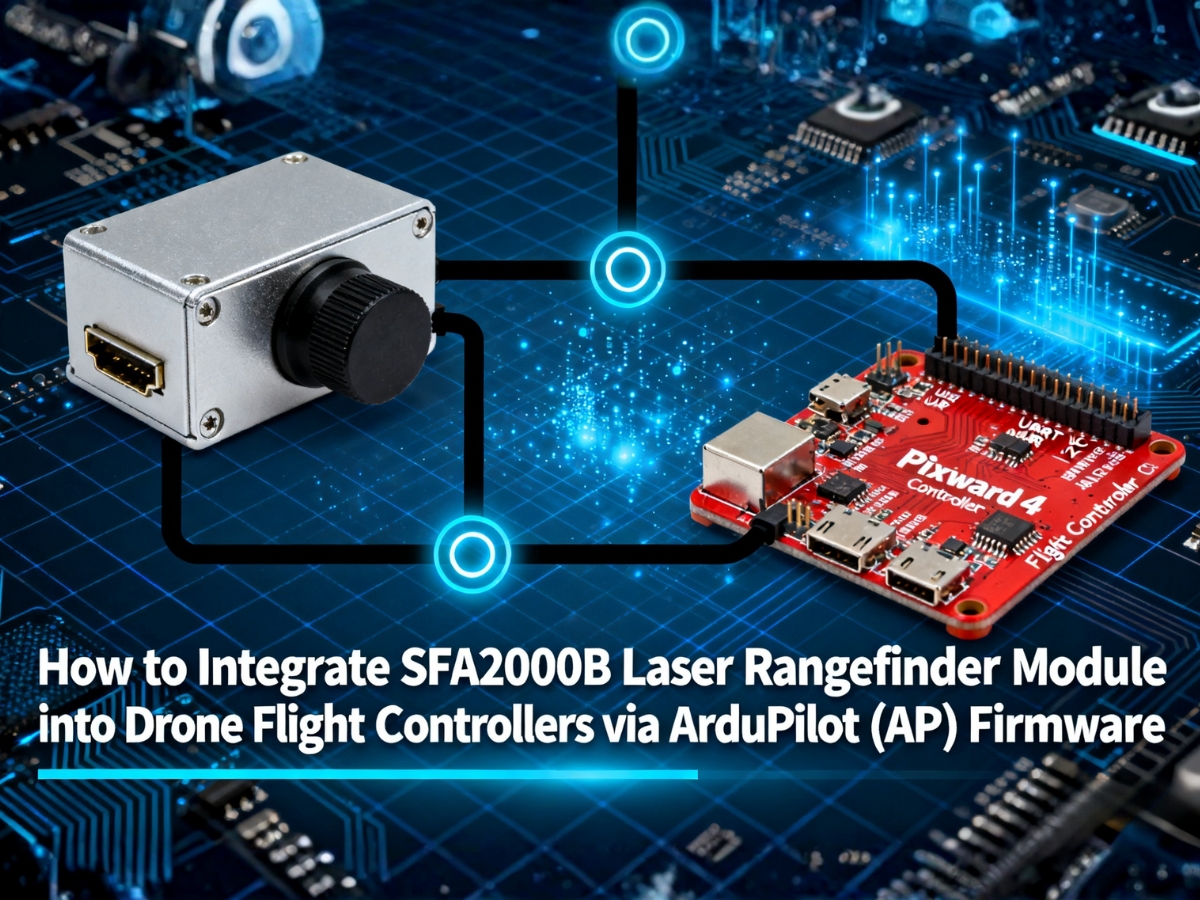
Step 2: Wire the SFA2000B to the Flight Controller
Now connect the module to the flight controller’s free UART port (we’ll use TELEM2 for this example).
2.1 Wiring Diagram (Pixhawk 4 + SFA2000B)
| Pixhawk 4 TELEM2 Pin | SFA2000B Pin | Description |
|---|---|---|
|
3.3V |
Pin 5 (VCC) |
Power (use external 3.3V/1A if 3.3V port is underpowered) |
|
GND |
Pin 6 (GND) |
Common ground |
|
TX (Flight Controller Send) |
Pin 2 (RXD) |
Flight controller sends ranging commands to the module |
|
RX (Flight Controller Receive) |
Pin 3 (TXD) |
Flight controller receives distance data from the module |
2.2 Critical Wiring Tips
- Shielded Wires: Use shielded cables for TX/RX to reduce EMI from motors (unshielded wires cause data corruption).
- Power Isolation: If the flight controller’s 3.3V port can’t supply 500mA, connect an external 3.3V/1A module (e.g., Pololu 3.3V Step-Down Regulator) to avoid brownouts.
- Pin Protection: Cover unused pins (e.g., Pin 1: Power-EN) with electrical tape to prevent short circuits.
Step 3: Configure ArduPilot (AP) Firmware Parameters
ArduPilot doesn’t natively support the SFA2000B’s protocol, so we’ll use the Custom Serial Sensor feature (AP 4.3.0+) to map the module’s data to the flight controller.
3.1 Connect Mission Planner to the Flight Controller
- Power the flight controller and connect it to your computer via USB.
- Open Mission Planner → Select the correct COM port → Click “Connect”.
- Go to the Config/Tuning → Full Parameter Tree tab (this is where we’ll edit all settings).
3.2 Configure the UART Port (TELEM2)
First, set up the flight controller’s TELEM2 port to communicate with the SFA2000B:
| Parameter | Value | Description |
|---|---|---|
|
SERIAL2_BAUD |
115200 |
Match the SFA2000B’s default baud rate |
|
SERIAL2_PROTOCOL |
23 |
Enable “Custom Sensor” mode (critical!) |
|
SERIAL2_OPTIONS |
|
No special options (set to 1024 if EMI is an issue) |
3.3 Configure the Rangefinder (RangeFinder1)
Next, tell ArduPilot to treat the SFA2000B as a rangefinder:
| Parameter | Value | Description |
|---|---|---|
|
RNGFND1_TYPE |
32 |
Select “Custom Serial” (for custom protocols) |
|
RNGFND1_MIN_CM |
300 |
Minimum range (3m = 300cm, match SFA2000B’s blind zone) |
|
RNGFND1_MAX_CM |
200000 |
Maximum range (2000m = 200000cm) |
|
RNGFND1_SCALE |
0.1 |
Convert module data (divide by 10: 20003 → 2000.3m) |
|
RNGFND1_ORIENT |
25 |
Mounting orientation (25 = Down, for altitude hold; 0 = Forward for obstacle avoidance) |
3.4 Define the SFA2000B’s Data Format
Finally, teach ArduPilot how to parse the SFA2000B’s hex response (frame: 55 AA 88 01 FF XX XX YY):
| Parameter | Value | Description |
|---|---|---|
|
CUST_SENSOR_TYPE |
1 |
Sensor type = Rangefinder |
|
CUST_SERIAL_PORT |
2 |
Use TELEM2 (port 2) for communication |
|
CUST_DATA_LEN |
8 |
SFA2000B’s response is 8 bytes long |
|
CUST_HEADER1 |
0x55 |
First byte of the frame header |
|
CUST_HEADER2 |
0xAA |
Second byte of the frame header |
|
CUST_DATA_OFFSET |
5 |
Distance data starts at byte 5 (XX in the frame) |
|
CUST_DATA_BYTES |
2 |
Distance data is 2 bytes (16-bit) |
|
CUST_ENDIAN |
|
Little-endian (check with your module—most SFA2000B units use little-endian) |
Step 4: Send Ranging Commands from the Flight Controller
The SFA2000B won’t send data unless it receives a command. We’ll use ArduPilot’s Lua scripting to make the flight controller send commands automatically.
4.1 Create a Lua Script
- In Mission Planner, go to Config/Tuning → Lua Scripts.
- Click “New Script” and paste the code below (sends a single ranging command every 1 second):
					-- SFA2000B Ranging Command Script (1Hz)
local serial_port = serial.open(2, 115200) -- Port 2 = TELEM2, 115200bps
local single_range_cmd = string.char(0x55, 0xAA, 0x88, 0xFF, 0xFF, 0xFF, 0xFF, 0x84) -- Single ranging command

-- Send command every 1000ms (1Hz)
function send_command()
    serial_port:write(single_range_cmd)
    gcs:send_text(6, "SFA2000B: Command Sent (1Hz)") -- Log to Ground Station
    return send_command, 1000 -- Repeat every 1 second
end

-- Start the loop
return send_command()
- Save the script as
sfa2000b_cmd.luaand click “Load Script” (the flight controller will run it on startup).
4.2 For Continuous Ranging (5Hz/10Hz)
To use the SFA2000B’s continuous mode (e.g., 10Hz for fast-moving drones), replace the single_range_cmd with a continuous command:
- 5Hz command:
55 AA B9 FF FF FF FF D4(checksum = 0x55+0xAA+0xB9+0xFF*4 = 0xD4) - 10Hz command:
55 AA C9 FF FF FF FF C4(checksum = 0x55+0xAA+0xC9+0xFF*4 = 0xC4)
Step 5: Validate the Integration
Once all settings are saved, reboot the flight controller and verify the data is flowing correctly.
5.1 Check Real-Time Data in Mission Planner
- Go to the Status tab → Look for the “RangeFinder1” value.
- It should match the actual distance to the target (e.g., 5.2m if the drone is 5.2m above the ground).
- If it shows “0” or “NaN”, recheck your wiring and parameters.
- For visual confirmation, go to the Flight Data tab → Select “Proximity” from the dropdown.
- If the module is mounted downward (RNGFND1_ORIENT=25), you’ll see the “Down” distance update in real time.
5.2 Field Test (Critical!)
- Place the drone 5m above a flat surface (e.g., a concrete floor).
- Confirm the RangeFinder1 value reads ~5.0m (error ≤ ±0.5m, per SFA2000B’s specs).
- Move the drone up/down slowly—ensure the distance updates smoothly (no jumps >1m).
FAQ: Common Issues & Solutions
Q1: The flight controller shows no RangeFinder data, but the SFA2000B works with the USB-TTL adapter.
- Check if TX/RX are reversed (flight controller TX → SFA2000B RXD; flight controller RX → SFA2000B TXD).
- Verify
SERIAL2_PROTOCOL=23(not 1 for MAVLink) andCUST_HEADER1=0x55,CUST_HEADER2=0xAA. - Ensure the Lua script is loaded (check Mission Planner’s “Messages” tab for “SFA2000B: Command Sent”).
Q2: The distance data is jumpy (e.g., 5m → 12m → 3m).
- Replace unshielded wires with shielded ones (ground the shield to the flight controller’s GND).
- Use an external 3.3V/1A power module (the flight controller’s 3.3V port may be unstable under load).
- Clean the SFA2000B’s optical window with a lens cloth (dust causes reflection errors).
Q3: The SFA2000B returns a status of 0 (failure: 55 AA 88 00 FF FF FF YY).
- The target is in the module’s blind zone (≤3m)—move the drone farther away.
- The target has low reflectivity (e.g., trees, water)—test with a concrete wall.
- Sunlight is dierectly exposure to the module’s receiver—shield the lens or test in shade.
Q4: Can I use the SFA2000B for obstacle avoidance (not just altitude hold)?
- Set
RNGFND1_ORIENT=0(Forward) or1(Backward) in the parameters. - Use a continuous ranging command (5Hz/10Hz) in the Lua script for faster updates.
- Pair with ArduPilot’s “Obstacle Avoidance” feature (enable
AVOID_ENABLE=1).
Final Notes
The SFA2000B is a powerful rangefinder for drones, but its custom protocol requires precise configuration to work with ArduPilot. By following this guide—testing the module first, wiring carefully, and configuring parameters step-by-step—you’ll achieve reliable distance data for altitude hold, obstacle avoidance, or mapping.
If you encounter persistent issues, contact:
ArduPilot Community: Forums (expert help with firmware/parameters).